|
Micro Encoder Assembly
|
|
Page 7
|
| |
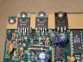
Gather the three
voltage regulator IC's, aluminum heatsink, nylon spacers, screws, lock
washers, and nuts. Following the manual bend the leads in the specified
pattern.
Attach the heat
sink to the board with two screws, shoulder washers, nylon spacers, lock
washers, and nuts.
Insert the three
voltage IC's. Attach each with a pan head screw and lock washer.
|
|

|
|
|
|
|
Locate the three small ferrite
noise suppression beads. Install with a clipped lead at L-1, L-2, and
L-3.
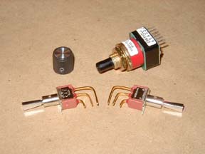
Get the two toggle switches.
Insert and make sure the sit strait and flush. Solder the leads.
|
|

|
|
|
|
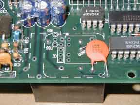
The big black
cube comes next. Straiten the leads if the are bent. There are many holes
in this section of the board that are not used. So make sure that the
cube lines up with the dashed outline on the CPU board. Install the cube
from the solder side. Make sure it sits flush. Solder and clip.
Locate the disc
capacitor marked 103Z. Install flat as shown in the photo and manual.
|
|

|
|
|
|
Clean
and inspect all boards for acceptable solder joints. Fix any that do not
pass.
|
| |
|
|
|
|
|