|
Micro Encoder Assembly
|
|
Page 6
|
| |
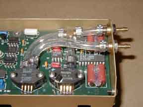
Locate 8 large
cup socket pins. Install at the two sensor positions. Do
not solder yet. Bend the leads of the sensors
so that the insert into the socket cups. Using the white nylon spacers
and the four long screws, mount the sensors. Position the
two temp sensor leads in to the PC board holes. Turn the cup socket pins
to capture the sensor leads. Solder the leads and the socket pins to the
board. Clean and inspect your solder joints fix any that don't pass. Apply
some RTV adhesive to the four large capacitors for vibration resistance.
|
|

|
|
|
|
|
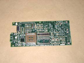
Gather the CPU board and the
sort cards. Following the manual insert all the resistors. Solder and
clip the leads. Install the last little blue trimpot and the yellow resistor
network. Follow this with the Diodes and capacitors. Solder and clip.
Resistor R67 is soldered to the solder side of the board. Insert the fuse
and CPU clock crystal. Solder and clip. Use a cut off lead to hold the
crystal from moving.
|
|

|
|
|
|
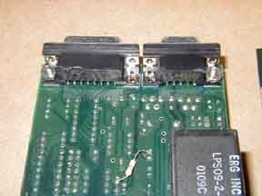
Get the two D-sub
connectors and insert from the solder side of the board. The prongs at
the outside of the assembly need to be cut off before soldering. Solder
just the end pins and make sure the connectors lie flush. Finish the rest.
Clean and inspect the assembly.
|
|

|
|
|
|
|
| |
|
|
|
|
|