|
Micro Encoder Assembly
|
|
Page 4
|
| |
Locate all the
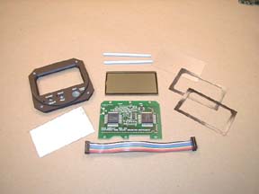
display board components and the two sort cards. Observe
all antistatic procedures. Use the faceplate as a guide and cut
the two black plastic gaskets to size. The resistors are installed vertically
so only one lead needs to be bent. Following the manual and install all
of the resistors. Bend the leads slightly, solder, and clip the leads.
Install the little blue trimpot, capacitors, and diodes. Solder and clip.
Get the special temp sensor from the black antistatic box. Install on
the solder side of the board.
|
|

|
|
|
|
|
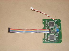
The temp sensor is tricky
so be careful! The polarity bump is very small so get a magnifying glass
to help. Put the last test point clip on the board and solder. Install
the two socket cups for the EL backlight from the solder side. Cut the
red and white wires with the crimp connectors on them in half. Insert
into the white terminal housings noting polarity. Twist the wires together.
Strip 1/4" of insulation from the ends and solder to the display
board. Follow with the colored ribbon cable. Clean and inspect all solder
joints.
|
|

|
|
|
|
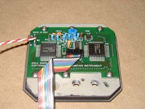
Place a gasket
into the face frame, followed by the antiglare plastic lens, the other
gasket, and the LCD screen. Clean and install the two zebra connectors.
The EL Backlight comes next with the pins in the upper left of the faceplate.
Install the display driver board ensuring that the two backlight leads
go into the two sockets. Use 6 screws to attach the board. Screw them
down to they all just touch, then tighten 1/4 turn at a time until they
are seated. Install the rotary switch.
|
|

|
|
|
|
Take the other
red and white wires with the crimp connectors on them, insert into the
white terminal housings noting polarity. Twist the wires together. Strip
1/4" of insulation from the ends and solder to the audio transducer.
Remove the "remove after washing" seal. Attach the transducer
to the face frame using two small dots of epoxy. Set assembly aside 'til
later.
|
| |
|
|
|
|
|