|
Micro Encoder Assembly
|
|
Page 3
|
| |
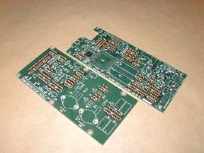
After
putting the socket pins in the two PC cards following the directions in
the assembly manual. Take the small piece of glass and place on top of
one of the cards and turn it over keeping the socket pins from falling
out. Solder every fourth pin. Turn the card back over and inspect for
pin straitness.
|
|
|
|
|
|
|
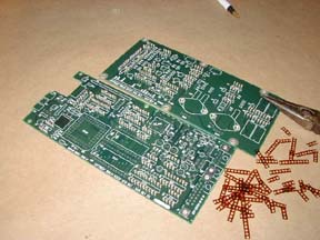
Flip
the card and finish soldering the rest of the pins. Repeat for the second
card.
Inspect all pins for straitness
and all solder joints for acceptable quality. Fix anything that does not
pass inspection.
Take your needle nose pliers
and grab a corner of the plastic strip holding the pins together and pull
off leaving the socket pins behind.
|
|
|
|
|
|
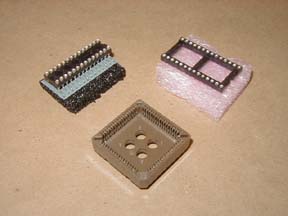
Get the CPU board,
locate the three IC sockets, the J-1 to J-4 header pins, and a test point
clip. (It looks like a small cotter pin with a pink collar) Install and
solder the J-1 and J-3 headers noting orientation. Install J-2 and J-4
making sure they both sit flush to the PC Board. Install the square 68
pin CPU socket noting orientation and make sure it sits flush. Install
the 28 pin narrow IC adapter at U-27. The last 28 pin socket needs to
be modified by removing the front cross rail with the notch in it.
|
|
|
|
|
|
Solder a few
pins, turn over and inspect for the socket sitting flush. Finish soldering
the rest of the pins. Inspect for acceptable solder joints. Get the A/D
board and the two remaining test point clips. Install one at the hole
marked AGND and the other at the hole marked 4.0000v. Solder both clips.
|
| |
|
|
|
|
|

