|
RST Audio Panel Assembly
|
|
Page 1
|
| |
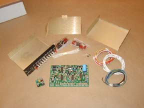
This
is what is included with the RST-565 Audio Panel Kit. I was doing an all
nighter at work printing 150 copies of a 300 page book. In between feeding
the printer a load a paper every 20 minutes I was able to get the components
inserted and soldered. I did not have my camera with me to take photos
of the steps because I am in a DOD closed area and cameras are not allowed.
Read the manual very carefully. It had me scratching my head many times
to figure things out. It could use a major rewrite in plain language.
|
|
|
|
|
|
|
I
found out later after an email to Jim at RST that two diagrams I needed
were in the second pack of papers titled Operation and Maintenance. I
think they should have been inserted into the assembly manual at the appropriate
places. Right where you need them. One is a large printout of the Silk
screen from the PC board. That will help you locate component placement
on the board. I can't find a rhyme or reason for the numbering scheme
for the components. The numbers go from one side of the board to the other,
then to the middle, then bottom, and top.
|
|
|
|
|
|
Compared to the
two Rocky Mountain kits I have assembled, I consider this one to be two
steps more difficult in the assembly process. Mainly due to the instructions
and component numbering on the printed circuit board. All the resistors,
capacitors, diodes, and other components come in one large bulk package.
I had some machined socket pins left over from the Rocky Mountain kits,
so I used them for the ICs in this kit.
|
|
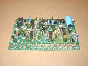
This is the finished
board except for the hook up wires.
After it was
finished I had two capacitors left over. I thought I had missed them somewhere.
After a thorough search of the assembly instructions and counting the
caps on the board I came to the conclusion that they were extra. I did
not write the quantity down, so, I would have known that sooner. I lost
an hour of time to find that out.
|
|
|
|
Do
yourself a favor and get a magnifying glass. Sort all of the components
by their color codes and values. Tape them to a piece of paper and label
them with their quantity,
value, and color code. This will make finding the right part easier. Tear
out or make a second copy of the PC board component numbering page from
the maintenance and operation "book." It will make finding locations
a little bit easier.
|
| |
|
|
|
|
|

